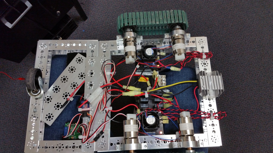
First, I'll give some context - I recently finished working on a project in which some students motorized an old R2-D2 themed Pepsi cooler thing, and I set up all the electronics for, including a repurposed flight controller that mixed the RC signals from the cheapo transmitter/receiver set.

Initially, the robot had no onboard computer or brain of any sort. The motors were directly controlled by the radio receiver, with each side controlled by the vertical axis of each stick. This made it difficult to drive, for a variety of reasons. From the beginning, I planned to have it driven arcade style - only using one stick, with vertical being forward/backward and horizontal being steering. The task, therefore, was to take two RC signals in arcade configuration as input, do some math on them to make them into tank drive, or a value for each side of the drivetrain, and output them as two RC signals. I had hoped to simply use an old ArduPilot flight controller loaded with the APM:Rover firmware, but unfortunately all of our ArduPilots were nowhere to be found. The easy solution from that point would have been to use an Arduino, but I wanted something a bit more compact, and with PWM headers. A programmable flight controller fits that bill fairly well, and even though I couldn’t find an ArduPilot, I had a different kind of flight controller sitting on my desk.
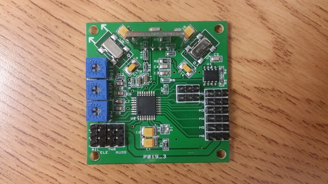
The “HobbyKing Multi-Rotor Control Board V3.0”, based on something from KK MultiCopter. The documentation was about as informative as the name, and the firmware was closed source, but what I could tell was that it had an AVR microcontroller and an ISP header. That was good enough for some simple RC input and output, with the added benefit that I have been working with AVRs for a while now, using Arduino. While Arduino was an option for this project, I have written board definitions in the past and just didn’t feel the urge to do it again for a one-off project. Instead, I took this as an opportunity to learn the Atmel Studio workflow, something I had been meaning to do for a while.
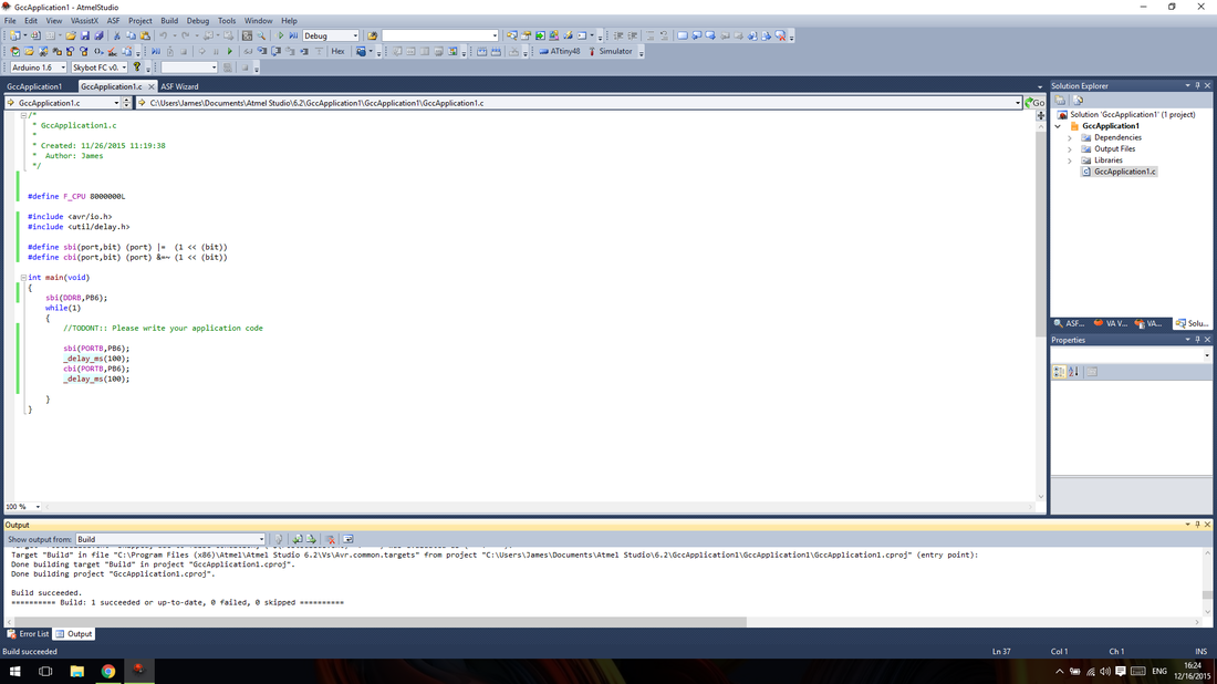
I was hit with some major differences from Arduino off the bat - I had done one thing without Arduino before, so I knew that many of the usual functions would be gone, but I was surprised to find that super simple stuff such as a delay function and a system time were missing. Delay was as easy as including a header and specifying the system speed, but a system clock, which was necessary for RC input, was not so quick. To have that sort of clock, one of the timer/counters had to be used as just that - a timer, counting up forever. The timer ticks up by 1 every time it receives a pulse from the clock source (hence, the name “counter”), to a maximum value of 256, as it is an 8-bit timer. The system clock on this board was 8 MHz, or 8 ticks per microsecond. Since microseconds were my desired unit, I used the prescaler functionality of the timer to make it tick up once every 8 clock cycles. However, the 8-bit nature of the timer meant that it could only keep track of 256 microsecond intervals. The RC signals it needed to decode were between about 1000 and 2000 microseconds long, so this was an issue. The solution is simple, however: The timer can be set up to run an interrupt every time it overflows, or goes back to zero. In this interrupt, a variable is set to increment by 1. So, the number of microseconds since the timer was turned on is the current value of the timer plus the number of overflows times 256. Seems simple enough, but I couldn’t get it working. After a few hours of trying to implement my own system timer, I ended up just using an excerpt from the Wiring library, which is part of Arduino.
Having the groundwork out of the way, the next challenge was to actually input and output those RC signals. This was a bit daunting, so I referenced the code of MultiWii as a starting point, having previously read through most of it. I started with input, as it’s a good thing to have when generating output. The general concept of reading the RC signals is that the time between pulses is recorded, and if it’s a sane value (between the expected minimum and maximum), it’s accepted as the input value. This is accomplished by setting up the AVR to fire an interrupt every time the input pins change, and then running a short burst of code for that interrupt (the “Interrupt Service Routine”, or ISR) which tracks the change in time for each pin. In order to prevent the interrupt running for pins I don’t care about and clogging up the CPU, only the Pin Change Interrupt (PCINT) for the bank of pins the RC input is on is enabled, and a mask (PCMSK) is applied to that interrupt so only the RC input pins trigger it. AVR pins are divided into ports, which are sets of bytes, so all the pins are in groups of 8, and have to be accessed in those groups. Fortunately, all the input pins were on one port and one PCINT bank, so things were a bit easier than they could have been.
When the ISR for the pin change runs, interrupts are disabled (to prevent interrupting the time-sensitive parts), the current time is recorded, the change in the RC pins is recorded (by applying a logical XOR to the current port value and the last recorded port value), and interrupts are re-enabled. Then, a for loop iterates through an index of the RC input pins, which contains their position in the port (a bitmask with the pin in question as a 1). For each pin, the previously found change is compared to the pin position with a logical AND, and if the result is boolean true, then the change in time is found for that pin by subtracting the last recorded time from the current time. If that value is within the expected limits, that is, between 900 and 2100 microseconds, it is recorded as the RC input value for that pin/channel. Otherwise, the value is discarded. Then, the current time is recorded as the new last time for that channel, and the for loop continues. After that’s done, the current port value is recorded as the new last port value, interrupt concludes, and we have our RC inputs.
The major disadvantage of these boards versus Arduino is that they have no USB interface, and the serial pins are hooked up to some trimpots. While programming is still easy enough, there isn’t any easy way to extract real-time data from the boards. So, whether or not my code was working was basically a guess, and I didn’t want to tackle output until I knew input was working. The only method of communication I had readily available on the board was the status LED. So, I set up the main loop to turn on the LED if the channel 0 input was above 1500 microseconds (the expected midpoint for RC PWM). Unsurprisingly, it didn’t work the first time. Since the program was and still is very small, I simply changed the conditions for turning on the LED and recompiled until it came on, then changed them a few more times until I knew what values my code was returning and how they corresponded to the actual output of the receiver. As it turned out, my code was actually fine the first time, I had just mistakenly set the maximum input value to 1100 instead of 2100, causing the code to throw out everything (my controller strangely didn’t have the expected full range, so it never got to 1100). Having solved input, it was time to tackle output.
The RC output is based around a single 16-bit hardware timer, which drives both the output pins. This was a bit more foreign and challenging to me than the input code, as the timers are controlled by registers and code that has no clear meaning without thoroughly studying the datasheet. The concept is fairly simple: have a timer that resets every 20 milliseconds, and set the output pin high if the timer is currently below the desired output value (between 1 and 2 milliseconds), otherwise set it low. Actually getting the timer to cooperate is the challenging part. I read the datasheet’s chapter on Timer1 (the 16-bit one) many times over, and studied MultiWii’s output code before attempting anything. A quick note: how I implemented RC output is not necessarily the best way to do it. I don’t know what the maximum refresh rate on my motor controllers or most motor controllers is, so I settled for 50Hz and aimed to replicate the output of the radio receiver, at the cost of some precision.
The timer is configured using 3 registers TCCR1A, B, and C (Timer/Counter Control Register 1 A, B, and C). These define how fast the timer runs, what its max value is, and how the output pins are controlled. The registers are set using atomic logical ORs and ANDs, although they could just be set to a value since no other part of the program is or should be using them. I set the prescaler value to 64, meaning the timer ticked up once every 8 microseconds, and meaning that my output had a precision of 8 microseconds, which is about equivalent to 7 bits of precision for the range I was outputting in. Probably not good enough for flight control, but fine for a simple ground vehicle. I then set the Waveform Generation Mode to mode 3, 10-bit Phase Correct PWM. “Phase Correct” is important here - in short terms, is means the output waveforms are back to back, which effectively halves the frequency and doubles precision. This means I actually get about 8 bits of precision, which is what I wanted and expected. Lastly, I set both the output compare pins to mode 2 (COM1n1:0=2) so that they output the desired waveform. With the timers properly set up, the only thing left to do is set the Output Compare registers, which tell the timer when to turn the output pins on or off. The difficulty there is that my output value is in microseconds, but the timer is running at 8 microsecond intervals, and back to back. The solution seemed clear: divide my output value by four. My logic might be flawed, but what matters is that it didn’t work. The actual output was way off from what I expected, and in an odd way. I didn’t write down what the initial results were, and I’m writing this from a different computer so I don’t know numerically what exactly I did. Basically, I divided my output value by a constant, and subtracted another constant from that. Similar to testing with the LED earlier on, I just changed constants, recompiled, and repeated until I got the output I wanted. Not necessarily elegant, but effective and reliable.
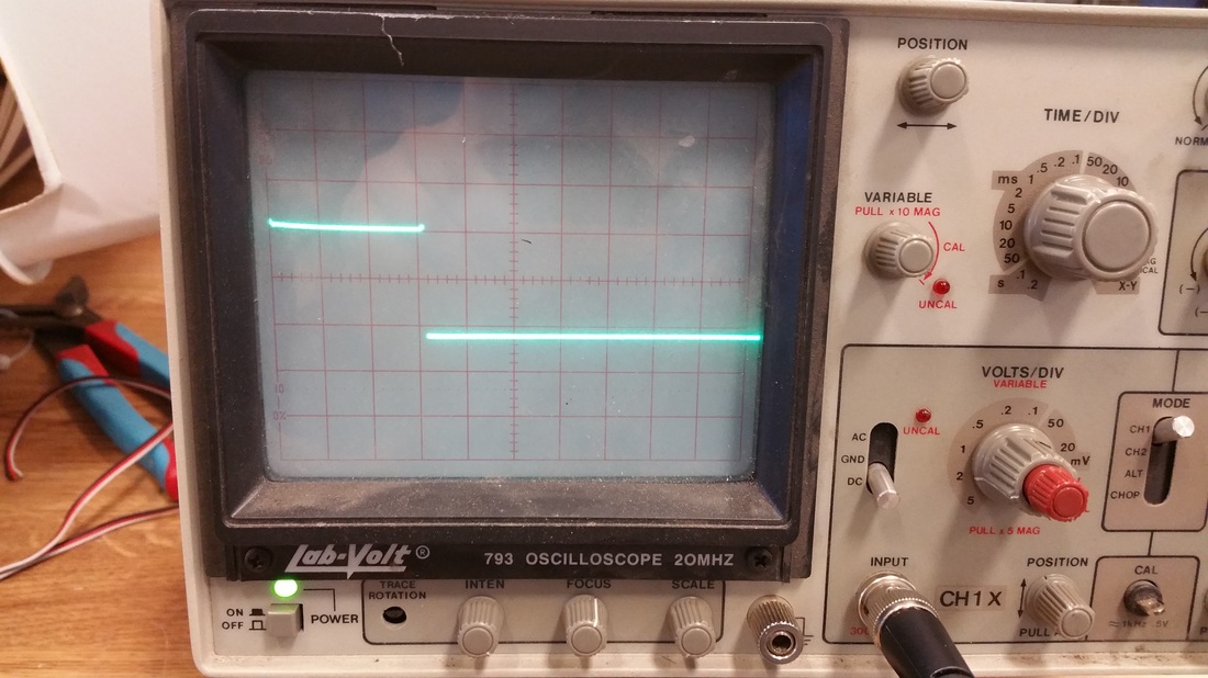
I ran into a major roadblock when writing the output code: for a while, I was compiling and running code (out of desperation, at one point I just compiled the MultiWii code), and I was getting basically no output. The first few times, my waveform was sort of visible at the microvolt level and with completely wrong timing, but the correct response to the input. I spent an hour or so getting no results, then left it for a while. Then when I came back for round two, I just got electrical noise. No changes to the code could get any sort of output on those pins. I realized then that I had forgotten to set the output pins as outputs, by setting them high in the Data Direction Register. So I set them as outputs, and still got electrical noise. I put a simple blink program on it and confirmed that they were outputs, could be set high, and that my oscilloscope was working. I kept playing with it for another hour with no changes, which was very confusing, so I called it a day at that point. When I came in the next morning and turned everything on, the waveform was there on the oscilloscope as expected. I’m really not sure where it all went wrong, but it was probably tunnel vision of some sort. At that point I started changing my coefficient and offset to get the waveform I wanted, but that’s just a great example of how sometimes just taking a break and restarting can solve problems.
The timer is configured using 3 registers TCCR1A, B, and C (Timer/Counter Control Register 1 A, B, and C). These define how fast the timer runs, what its max value is, and how the output pins are controlled. The registers are set using atomic logical ORs and ANDs, although they could just be set to a value since no other part of the program is or should be using them. I set the prescaler value to 64, meaning the timer ticked up once every 8 microseconds, and meaning that my output had a precision of 8 microseconds, which is about equivalent to 7 bits of precision for the range I was outputting in. Probably not good enough for flight control, but fine for a simple ground vehicle. I then set the Waveform Generation Mode to mode 3, 10-bit Phase Correct PWM. “Phase Correct” is important here - in short terms, is means the output waveforms are back to back, which effectively halves the frequency and doubles precision. This means I actually get about 8 bits of precision, which is what I wanted and expected. Lastly, I set both the output compare pins to mode 2 (COM1n1:0=2) so that they output the desired waveform. With the timers properly set up, the only thing left to do is set the Output Compare registers, which tell the timer when to turn the output pins on or off. The difficulty there is that my output value is in microseconds, but the timer is running at 8 microsecond intervals, and back to back. The solution seemed clear: divide my output value by four. My logic might be flawed, but what matters is that it didn’t work. The actual output was way off from what I expected, and in an odd way. I didn’t write down what the initial results were, and I’m writing this from a different computer so I don’t know numerically what exactly I did. Basically, I divided my output value by a constant, and subtracted another constant from that. Similar to testing with the LED earlier on, I just changed constants, recompiled, and repeated until I got the output I wanted. Not necessarily elegant, but effective and reliable.
I ran into a major roadblock when writing the output code: for a while, I was compiling and running code (out of desperation, at one point I just compiled the MultiWii code), and I was getting basically no output. The first few times, my waveform was sort of visible at the microvolt level and with completely wrong timing, but the correct response to the input. I spent an hour or so getting no results, then left it for a while. Then when I came back for round two, I just got electrical noise. No changes to the code could get any sort of output on those pins. I realized then that I had forgotten to set the output pins as outputs, by setting them high in the Data Direction Register. So I set them as outputs, and still got electrical noise. I put a simple blink program on it and confirmed that they were outputs, could be set high, and that my oscilloscope was working. I kept playing with it for another hour with no changes, which was very confusing, so I called it a day at that point. When I came in the next morning and turned everything on, the waveform was there on the oscilloscope as expected. I’m really not sure where it all went wrong, but it was probably tunnel vision of some sort. At that point I started changing my coefficient and offset to get the waveform I wanted, but that’s just a great example of how sometimes just taking a break and restarting can solve problems.
With RC input and output written and reliable, the hard part was over. From there I basically just had 2 inputs, 2 outputs, and some simple math in between. I made channel 1 my acceleration and channel 2 my steering, and subtracted 1500 from the steering to give it a range of plus or minus 500. Then I just added steering to acceleration on one channel, and subtracted steering from acceleration on the other. Compiled, tested, had the steering reversed, reversed the steering, compiled again, and had it working the way I wanted. At that point, I saved everything, cleaned out broken code and old bits from my code, figured out what I needed to do to comply with the LGPL that the Wiring library is under, and called it done. I will be posting the code in question somewhere soon.
I went into this project knowing that it would be a challenge and knowing that there were easier ways, and it was every bit as fun as I expected. Staring at code for hours wondering why it’s not working and what could possibly be wrong is never fun, but getting to see the results when something finally works keeps me going, and the final functional product is always exciting to see, which definitely makes the whole process worth it. From a board that did nothing, to a Blink program, to an exploration of interrupts and timers, to a fully functional board that converts arcade drive to tank drive, the process was a great learning experience and goes to show that something seemingly simple like inputting and outputting a few RC signals can actually be a complex problem. Finding documentation and tutorials for my particular application was tough, so hopefully this article and the accompanying code can be of assistance to anyone trying to do something similar. Thanks for reading!
Update Jan. 14, 2016:
Here is the source code that this article discusses:
| r2d2controlmixer.zip |
 RSS Feed